- This manual is designed for the usage of X100 PAD2, applying to X100 PAD2 smart automotive diagnosis platform.
- Use the device only as described in this manual. The user will be responsible solely for the after-effects of violating the laws and regulations caused by using the product or its data information; in this case Xtool will not bear any legal responsibility.
- Xtool shall not be liable for any incidental or consequential damages or for any economic consequential damages arising from the accidents of individual users and the third parties, misuse or abuse of the device, unauthorized change or repair of the device, or the failure made by the user not to use the product according to the manual.
- All information, specifications and illustrations in this manual are based on the latest configurations and functions available at the time of printing. Xtool reserves the right to make changes at any time without notice.
1. Diagnostic Link Connectors Locations of Various Vehicle Models

*AUDI A6: the OBD plug is on the lower left side of the dashboard, use SMART OBDII-16 connector.
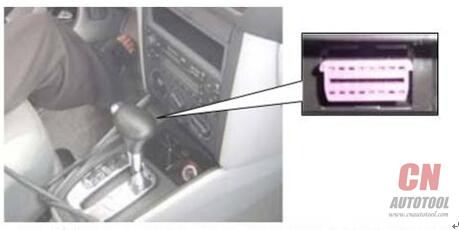
*VW Bollywood 1.8: the OBD plug is below the console, use SMART OBDII-16 connector.
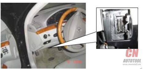
*Benz S320,220 Chassis: the OBD plug is below the dashboard, use SMART OBDII-16 connector.
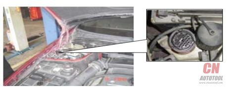
*Benz C180: the OBD plug is on the left hand side of the engine bay, use Benz-38 connector.
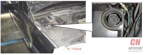
*Benz 300SEL 140 chassis: the OBD2 Scanner is on the left hand side of the engine bay, use Benz-38 connector.
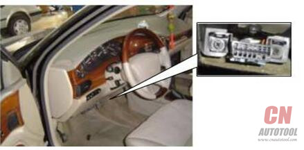
*GM Buick: the OBD plug is below the dashboard, use SMART OBDII-16 connector.
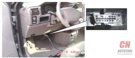
*GM Buick GL8 : the OBD plug is below the dashboard, use SMART OBDII-16 connector.
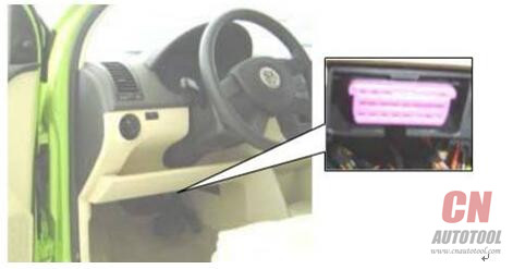
*VW POLO: the OBD plug is below the dashboard, use SMART OBDII-16 connector.
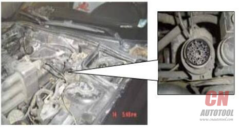
*BMW 735I: the Xtool Scanner is in the right hands side of the engine bay, use BMW-20 connector.
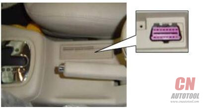
*VW Passat B5: the OBD plug is behind the gearlever and beside the parking brake lever. Lift the cover to access it. Use SMART OBDII-16 connector.
2. Location Diagram of Vehicle Diagnostic Link Connectors
Location diagram of pick-up truck diagnostic link connectors:

Location diagram of utility vehicles diagnostic link connectors:

Link diagram of small car diagnostic link connectors:

NOTE: Each vehicle manufacturer may use additional pins to diagnose a variety of systems. Not every manufacturer uses the same standard. The function on a certain pin will vary from manufacturer to manufacturer. Verify with the manufacturer.
3. Diagnostic Link Connectors Terminal Definition and Communication Protocols
3.1. Standard OBDII Diagnostic Link Connector:
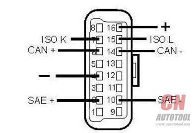
Pin Definition (Reference material)
Various pin definitions as follows:
1. Manufacturer definition
2. SAE J1850 bus positive
3. Manufacturer definition
4. Bodywork site
5. Signal site
6. ISO 15765-4 defined CAN high
7. ISO9141 and ISO14230 defined K line
8. Manufacturer definition
9. Manufacturer definition
10. SAE J1850 bus negative
11. Manufacturer definition
12. Manufacturer definition
13. ISO 15765-4 defined CAN low
14. ISO9141 and ISO14230 defined L line
15. Permanent positive voltage
[1] 1, 3, 8, 9, 11, 12 and 13 are defined by manufacturer.
[2] 2, 6, 7, 10, 14 and 15 are used for diagnostic communication. Unused definitions can be defined by manufacturers.
没有评论:
发表评论